






Snap Button Tolerances Explained: How Manufacturing Variation Changes Fit, Force and Consistency

A snap button specification can show every nominal dimension correctly and still produce inconsistent production. One lot closes smoothly, another feels unusually tight, and a third begins to rattle after a short period of use. The problem is often not that every part is outside its drawing limits. It is that socket, stud, spring, finish and installation variations combine differently across the assembly.
Tolerance engineering asks a more useful question than “Does this part pass?” It asks whether the full distribution of finished components—and the combinations created when those components are assembled—will remain inside a validated functional window. For press studs for garment manufacturing, that window must cover component dimensions, operating force, attachment security, surface condition and performance on the intended fabric stack.
This article focuses on production variation and consistency. Here, the emphasis is how those dimensions spread, shift, interact and are controlled during repeat production.
The Short Answer: A Tolerance Is Not the Same as Process Variation
A tolerance is the permitted range written in a specification. Process variation is the distribution the manufacturing process actually produces. They are related, but they are not interchangeable.
For example, an effective socket opening may be specified as 3.90 ± 0.03 mm. That creates a lower specification limit of 3.87 mm and an upper specification limit of 3.93 mm. A stable process centered at 3.90 mm with a narrow spread can produce consistent parts. A process centered at 3.925 mm may also ship many parts within the same limits, yet it leaves little margin on one side and moves the socket–stud fit toward the loose boundary.
The complete snap experiences the combined result:
Functional fit = socket distribution + stud distribution + spring variation + finish variation + assembly and installation variation
That is why conformance of individual components does not automatically prove consistency of the finished pair. The tolerances must be allocated around functional sensitivity, and the processes must be both stable and capable of holding the intended center.
Five Numbers Buyers Should Not Confuse
| Term | What it means | What it does not prove |
|---|---|---|
| Nominal dimension | The target or named size used to define the design | That production is centered on the nominal |
| Specification limits | The agreed maximum and minimum acceptable values | That the process is statistically stable or well centered |
| Observed process spread | The variation measured across parts, cavities, time and lots | That the measurement method is accurate enough to reveal the true spread |
| Control limits | Data-based boundaries used to detect unusual process behavior | Product acceptance; control limits are not customer specification limits |
| Functional window | The range in which the completed snap closes, seats, releases and remains attached as required | That every individual drawing tolerance has been optimally allocated |
A useful specification connects all five. It defines the nominal and limits, validates the measurement system, monitors the real distribution and proves that boundary combinations remain functionally acceptable.
Which Characteristics Need the Tightest Control?
Not every dimension deserves the same tolerance. Critical-to-quality characteristics are the features whose variation materially changes fit, force, attachment or appearance. For a metal snap assembly, they commonly include:
- the effective free opening and roundness of the socket retaining structure;
- the stud’s maximum engagement profile, neck profile, transition radius and axial height;
- spring thickness, active length, formed angle, support position and permanent set;
- socket shell depth and the location of the spring within the shell;
- post, eyelet or prong length relative to the compressed substrate;
- final plated dimensions, surface buildup and burr condition;
- installed concentricity, socket ovality, stud tilt and completed stack height;
- closing and release force–displacement behavior on the approved combination.
A decorative cap outside diameter may tolerate more variation than the active stud profile, while a logo position may require strict visual control but have little influence on operating force. The right tolerance policy separates appearance characteristics, attachment characteristics and engagement characteristics instead of applying one blanket precision level.
How Tolerances Stack Across Socket and Stud
The active fit is produced by at least two distributions: the stud engagement profile and the effective socket opening. In a simplified diametral model:
Interference I = Dstud − Dsocket opening
The loosest arithmetic combination is the smallest stud with the largest socket opening. The tightest is the largest stud with the smallest opening:
Imin = Dstud,min − Dsocket,max
Imax = Dstud,max − Dsocket,min
Worst-case arithmetic is appropriate when every permitted extreme must assemble safely. It is conservative because it assumes all contributing features reach their adverse limits at the same time. For high-volume production, statistical stack analysis may also be useful, but only when the input distributions, correlations, centering and stability are understood.
A common simplified statistical estimate for independent, centered contributions is the root-sum-square method:
Combined standard deviation σstack ≈ √(σ12 + σ22 + … + σn2)
This method should not be used automatically. Dimensions produced by the same forming tool, plating rack or setting machine can be correlated. A shifted mean or mixed-cavity population can also make a single normal-distribution assumption misleading. Boundary builds remain essential for validating the real functional limits.
Manufacturing Variation Enters at Every Process Step
Blanking, Piercing and Stamping
Strip thickness, material condition, punch-to-die clearance, feed position and tool wear affect cut edges and formed dimensions. Burr growth can change how a spring seats or how a profile enters the socket. A feature measured as acceptable across two points may still develop lobing or local high spots that alter contact.
Forming the Socket and Stud
Forming depth, die alignment, lubrication, press load and springback determine final geometry. Material from different coils or heat lots can respond differently even when its chemistry meets the same grade requirement. Work hardening and residual stress also influence how the retaining element behaves under repeated engagement.
Spring Placement and Subassembly
A separate spring can vary in free opening, orientation and axial position. The shell may constrain it differently when crimping depth changes. A socket therefore needs inspection as an assembled functional component, not only as independent shell and spring pieces.
Plating and Surface Finishing
Finish buildup can increase an outside profile, reduce an internal opening, soften a radius or accumulate differently on exposed and recessed surfaces. Barrel load, rack position, current density and topcoat conditions add variation. A finish change can move both geometry and friction, so dimensional approval of unfinished parts cannot substitute for testing final finished components.
Final Setting on the Customer’s Substrate
Setting-force variation, die wear, post length, fabric compression and machine alignment can ovalize a socket or tilt a stud. This last step may create more functional spread than the loose-component dimensions. The control plan must therefore extend through installation on the actual material stack.
Process Centering Matters as Much as Tolerance Width
Two suppliers can use identical drawing limits and deliver very different consistency. Supplier A may operate close to the target with a narrow, stable distribution. Supplier B may have the same spread but run near one specification limit. A small tool-wear shift then creates defects or pushes most combinations toward one force extreme.
Process capability indices help describe this relationship. The NIST/SEMATECH Engineering Statistics Handbook defines commonly used indices including Cp and Cpk:
Cp = (USL − LSL) / 6σ
Cpk = minimum of [(USL − μ) / 3σ] and [(μ − LSL) / 3σ]
Cp compares the available tolerance width with process spread. Cpk also accounts for how close the process mean is to the nearer specification limit. A process can therefore have a relatively favorable Cp but a poorer Cpk when it is off center.
| Observed pattern | Likely interpretation | Action |
|---|---|---|
| Narrow spread, centered | Good margin to both limits | Maintain controls and monitor for drift |
| Narrow spread, off center | Process may be precise but aimed incorrectly | Recenter before tightening the tolerance |
| Wide spread, centered | Mean is correct but ordinary variation consumes the tolerance | Reduce variation at its process sources |
| Wide spread, unstable | Special causes or mixed populations may be present | Stabilize and stratify the process before capability analysis |
No universal capability target should be inserted into a snap specification without agreement. The required margin depends on safety, application, inspection strategy, production volume and customer risk. Capability indices are also meaningful only when the data and distribution assumptions are appropriate and the process is stable.
Control Limits Are Not Product Limits
Specification limits come from design and customer requirements. Control limits are calculated from process data to identify behavior that is unusual for that process. A part can fall inside a control chart’s limits yet violate the product specification if the process is centered incorrectly. A point can also trigger a control-chart signal while still being dimensionally conforming.
That distinction makes statistical process control useful. It detects shifts, trends, cavity differences or unusual events before final inspection finds a large number of nonconforming parts. For snap hardware, charts can be applied to socket opening, stud profile, spring position, plating thickness, installed height or force-test data when the sampling design reflects the actual process.
Data should be stratified where hidden populations exist. Mixing all cavities, presses, plating lines and setting machines into one average can make each subgroup’s movement difficult to see. Retain identifiers that allow a complaint to be traced back to tool cavity, coil or heat, machine, operator, finish lot and installation line.
The Measurement System Can Create False Variation
When a tolerance is small, the gauge and method must resolve the difference between genuinely different parts. The NIST gauge R&R guidance describes the need to characterize production measurement behavior, including repeatability and reproducibility; its broader measurement framework also considers stability and bias.
A practical gauge study for snap components should include:
- parts spanning the expected production range, not only nominal masters;
- multiple trained operators using the real work instruction;
- repeated measurements in randomized order;
- the actual fixture, probe, contact force and orientation;
- different gauges where more than one instrument is used;
- elastic socket features that reveal whether the gauge itself deflects the part;
- appropriate analysis of repeatability, operator effects, bias and long-term stability.
A snap fastener inspection standard should therefore define more than nominal values. It should identify datums, finished condition, measurement location, permitted contact force, fixture, instrument resolution, conditioning, calibration and the matching component revision.
ASME Y14.5-2018 (R2024) provides a general language for dimensioning and tolerancing, including datum and profile concepts. It does not prescribe snap-button performance, but it helps different laboratories interpret the same product definition consistently.
Force Testing Must Be Designed as a Distribution Study
One force value from one pair cannot describe manufacturing consistency. Testing should represent component lots, cavities, finish conditions, installation variation and the loose-to-tight combinations expected in production. A motorized test setup with controlled speed, alignment and data capture is more informative than a subjective hand check.
A button snap pull tester should record the defined direction, fixture, crosshead speed or loading procedure, conditioning, number of specimens and whether each result comes from a new pair or a previously cycled pair. Repeatedly testing the same snap may condition or wear it, so repeated-measures data must not be confused with independent part-to-part variation.
ASTM D4846-96(2021) covers the force required to disengage snap fasteners by pulls perpendicular and parallel to the plane of the fastener. ASTM also cautions that interlaboratory bias can affect acceptance results and recommends comparative testing when buyer and supplier results disagree. That warning is directly relevant to tight force tolerances.
A snap button pull off test may refer to attachment failure rather than mating release. ASTM D7142-05(2021) addresses the holding strength of a prong-ring attached to the socket or stud. It evaluates a different failure mode from unsnapping the socket–stud pair. A control plan must name the intended test instead of using “holding force” for both.
What to Record Beyond the Peak
- closing peak and release peak;
- travel to each peak and final seating position;
- force–displacement curve shape;
- specimen orientation and pull direction;
- component and finish lots;
- installed substrate, compressed thickness and setting parameters;
- change after an agreed number of cycles or conditioning steps.
Force data should be linked to the critical dimensions of the same specimens. Otherwise, the business learns that variation exists but not which process variable created it.
AQL Sampling Does Not Prove Process Capability
ISO 2859-1:2026 establishes attribute-based acceptance sampling schemes indexed by an acceptance quality limit for lot-by-lot inspection. This is useful for deciding whether to accept or reject a shipment based on counted defects.
However, snap button AQL inspection does not prove that every snap meets a continuous force requirement, nor does it show that the process is centered and capable. Attribute sampling reduces the amount of inspection; it does not eliminate sampling risk.
A snap button batch inspection plan should define lot formation, inspection level, defect classes, AQL values, sampling scheme, switching rules, disposition and reinspection rules. Critical dimensional or force characteristics may also need variable data, process-capability evidence or targeted boundary testing.
Practical distinction: AQL answers a lot-acceptance question. Statistical process control answers whether production is behaving consistently. Capability analysis answers how the stable distribution compares with specifications. Functional testing answers whether the complete installed assembly performs as intended.
Why a Lot Can Pass Dimensions but Still Feel Inconsistent
Several mechanisms can produce this result:
- Paired extremes: every socket and stud passes separately, but random pairing creates loose and tight combinations.
- Unmeasured profile variation: a two-point diameter passes while local lobing, radius or spring position changes contact.
- Mixed populations: cavities or tool stations have different means that disappear inside the overall average.
- Finish variation: plated dimensions and surface behavior change after the in-process measurement point.
- Installation distortion: the final setting operation moves the assembly outside its loose-component condition.
- Measurement noise: gauge variation is large enough to obscure the true part distribution.
- Force-test mismatch: different laboratories use different fixtures, speeds, directions or conditioning.
When buyers ask why snap buttons are hard to close, increasing tolerance width is rarely the first correct action. Preserve samples, identify the subgroup, measure the finished active profiles, verify alignment and installation, and compare the full force curve with a known-good lot. A broad tolerance may reduce rejects while leaving the customer’s problem unresolved.
Common-Cause and Special-Cause Variation Need Different Responses
Common-cause variation is the ordinary spread produced by a stable process: small changes in material, forming, measurement and environment. Reducing it usually requires process or tooling redesign, improved fixturing, better material control or a more capable measurement method.
Special-cause variation comes from identifiable events: a damaged punch, wrong spring revision, mixed component lot, plating excursion, incorrect setting die or machine misalignment. The response is containment and root-cause correction, not simply recalculating wider control limits.
Averages can hide both. Review time order and subgroup identity. A sudden step after tool maintenance, a repeating pattern by cavity or a trend across a plating run is more informative than one combined histogram.
Allocate Tolerances by Functional Sensitivity
Equal numerical tolerances are not automatically fair or economical. One feature may change operating force strongly, while another has little effect. One process may hold ±0.01 mm reliably; another may require expensive sorting to achieve it.
A disciplined allocation process is:
- define the acceptable functional window for closing, seating, release and attachment;
- identify the component and installed characteristics that influence that window;
- estimate sensitivity through controlled trials or designed experiments;
- measure the stable capability of each contributing process;
- allocate tolerance where it provides the greatest functional benefit;
- build loose and tight boundary combinations;
- confirm performance after finishing, installation, cycling and relevant conditioning;
- lock the approved center, limits and change-control rules.
The lowest manufacturing cost usually comes from controlling a small number of truly critical characteristics well, rather than applying very tight tolerances to every visible dimension.
A Practical Production Control Plan
| Control stage | Representative characteristic | Control method | Reason |
|---|---|---|---|
| Incoming material | Thickness, grade, condition and traceability | Certificate review plus defined verification | Material variation changes forming and spring response |
| Stamping/forming | Stud profile, socket opening, spring geometry | First-piece approval, in-process measurement and subgroup charts | Detects tool wear, drift and cavity differences |
| Finishing | Final dimensions, coating condition and appearance | Finished-part measurement and finish-lot traceability | Coating can change both fit and surface behavior |
| Component assembly | Spring seating, crimp position and shell geometry | Functional gauge plus dimensional sampling | Subassembly can shift the effective opening |
| Installation | Installed height, alignment, distortion and attachment | Approved dies, setting parameters and actual-substrate checks | The final state may differ from the loose component |
| Functional release | Force–displacement distribution | Defined fixture, sampling frequency and trend review | Confirms the complete system remains in its operating window |
A useful snap button quality control checklist should name the characteristic, specification, measuring method, frequency, subgroup, reaction plan, record owner and traceability fields. A checkbox that says “size OK” is not enough.
Change Control Protects a Validated Tolerance System
Consistency can be lost when a seemingly minor change bypasses revalidation. Examples include a new strip supplier, material temper, punch repair, forming lubricant, spring heat lot, plating chemistry, topcoat, component sub-supplier, setting die or substrate construction.
The change-control agreement should define which changes require notification, sample approval, capability data, dimensional comparison, force testing, cycling or compliance review. Tool refurbishment also needs a restart plan because the process mean after repair may not match the center before repair.
Golden samples are useful for comparison but cannot preserve the whole tolerance system. They wear and represent only one point. Retain controlled drawings, limit samples where practical, gauge records, approved test conditions, master component combinations and signed change history.
How Baocheng Supports Custom Tolerance Development
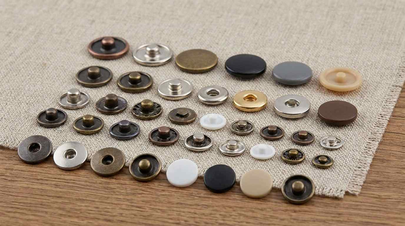
Baocheng (BC New Material) supplies finished snap-button products and customized precision components. As an OEM snap button manufacturer, Baocheng can work from the customer’s actual assembly requirements rather than relying only on a generic trade size.
Customization can cover socket or spring structure, stud profile, cap and post dimensions, logo details, material, finish, color, opening and closing behavior, critical tolerances and installation tooling. Samples can be set on the intended substrate stack so the final compressed geometry and force distribution are evaluated together.
This development approach addresses common B2B pain points:
- lot-to-lot force shifts despite nominally unchanged components;
- high sorting costs caused by tolerances that do not match process capability;
- parts that pass loose-component inspection but fail after setting;
- different cavities or finish lots producing visibly different force curves;
- buyer and supplier laboratories reporting inconsistent results;
- untraceable component mixing across suppliers or revisions;
- a successful prototype that cannot be repeated economically in volume production.
Baocheng can help convert subjective requirements such as “firm, smooth and consistent” into defined dimensions, measurement methods, force windows, boundary combinations and production controls.
JSW20 Adds Material Stability for Magnetic-Sensitive Projects
For needle-detection-sensitive and other magnetic-sensitive applications, Baocheng can supply finished snap products and custom components made from JSW20, its patented proprietary ultra-low magnetic permeability stainless steel. JSW20 is designed to retain extremely low magnetic permeability after forming, helping address the magnetic response that conventional stainless materials can develop through stamping and cold work.
JSW20 also provides resistance to chloride-containing corrosive environments. That combination is valuable when a product requires detector compatibility together with durability against perspiration, salt or cleaning exposure.
Material choice does not remove the need for tolerance control. Thickness, forming history, geometry, surface finish and contamination still affect the finished result. Baocheng therefore supplies JSW20 as completed hardware or engineered components—not raw coils or sheets—and can integrate material validation with dimensional, installation and functional requirements. REACH, RoHS, OEKO-TEX and nickel-release statements should be tied to the applicable product, finish, test report and project scope.
Buyer’s Tolerance and Consistency Checklist
- Define the complete four-part combination, revision, finish and intended substrate.
- Separate appearance, engagement and attachment characteristics.
- Identify critical finished dimensions and their datum references.
- State whether limits apply before or after plating and before or after installation.
- Validate the gauge method, fixture, contact force, calibration and operator reproducibility.
- Calculate arithmetic boundary combinations and evaluate statistical stacking only with justified assumptions.
- Confirm process stability before interpreting Cp or Cpk.
- Stratify data by cavity, machine, material lot, finish lot and setting line.
- Correlate critical dimensions with complete force–displacement curves.
- Use AQL sampling for its intended lot-acceptance purpose, not as a substitute for capability evidence.
- Approve final installed samples on the actual compressed substrate.
- Define reaction, containment and change-control requirements before mass production.
Conclusion
Snap-button consistency is created by a controlled distribution, not by a nominal dimension alone. Socket opening, stud profile, spring geometry, finish and installation each contribute variation. Even when every individual part passes its drawing, adverse combinations can shift the complete assembly toward loose or tight behavior.
A robust tolerance system connects product limits with process stability, measurement capability, boundary validation, statistical monitoring and functional testing. It distinguishes specification limits from control limits, process capability from AQL lot acceptance, and unsnapping force from attachment strength.
Baocheng can support this work through custom geometry, matched tolerance allocation, final-finish control, actual-substrate sampling, force testing and JSW20 ultra-low magnetic permeability stainless-steel solutions. The result is a snap system designed to remain consistent across cavities, lots and production locations—not merely a nominal drawing that one prototype happened to meet.
Focused FAQ
1. What is a snap-button tolerance?
It is the permitted variation assigned to a defined dimension or characteristic. It does not describe the actual production distribution unless process data are also collected.
2. Can every component pass inspection while the final snap still feels inconsistent?
Yes. Sockets and studs at different permitted positions can create loose and tight combinations. Finish and installation variation can widen the functional distribution further.
3. What is the difference between Cp and Cpk?
Cp compares process spread with tolerance width. Cpk also reflects process centering relative to the nearer specification limit. Both require appropriate, stable process data.
4. Are control limits the same as specification limits?
No. Specifications come from product requirements. Control limits are calculated from process behavior and are used to detect unusual variation.
5. Why should data be separated by tool cavity?
Different cavities can have different means or wear rates. Combining them can hide a shifted subgroup inside an acceptable overall average.
6. How does plating affect tolerance?
Plating can build on outside profiles, reduce internal openings and vary by geometry or process position. Final finished dimensions must therefore be included in approval.
7. Is AQL enough to assure consistent holding force?
No. AQL is an attribute-sampling method for lot acceptance. Continuous force consistency also needs capable measurement, variable data, process monitoring and functional correlation.
8. Why is gauge R&R relevant to small snap parts?
Operator technique, orientation, fixture force and gauge resolution can create apparent variation. A gauge study separates measurement effects from real part-to-part differences.
9. Should force be tested repeatedly on the same snap?
Only when cycling behavior is the stated objective. Repeated engagement can condition or wear the pair, so it should not be treated as independent production samples.
10. Which tests distinguish release from attachment?
ASTM D4846 addresses resistance to unsnapping in defined directions. ASTM D7142 addresses prong-ring attachment holding strength. They represent different failure modes.
11. Can Baocheng customize tolerances and operating force?
Yes. Development can include socket and spring structure, stud profile, cap and post dimensions, material, finish, critical tolerances, operating-force targets and validation on the intended substrate.
12. Does JSW20 eliminate manufacturing variation?
No material eliminates process variation. JSW20 provides extremely low magnetic permeability after forming and chloride-corrosion resistance, while the finished components still require dimensional, process and functional control.
#SnapButtonTolerances, #ManufacturingVariation, #SnapButtonConsistency, #ToleranceStack, #ProcessCapability, #SnapButtonQualityControl, #ForceTesting, #CustomSnapButtons, #JSW20, #BCNewMaterial