






How Snap Button Dimensions Affect Holding Force: Why Small Changes in Socket and Stud Size Matter
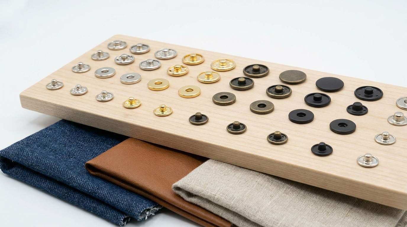
A snap button can look unchanged and still feel noticeably tighter or looser. The cause is often not a dramatic redesign. It may be a few hundredths of a millimeter at the active socket opening, the maximum stud engagement diameter, a transition radius, the seated neck or the installed height. Because these features work as a matched system, a small dimensional movement can change closing feel, release force, seating, wear and lot-to-lot consistency.
This is why “What size is the snap?” is an incomplete engineering question. Cap diameter is useful for appearance and product naming, but it does not define the mating geometry. A reliable specification must identify which dimensions control engagement, how they are measured, whether limits apply before or after finishing, and how the final installed assembly is functionally verified.
This guide concentrates on dimension definition, metrology and production control. It does not treat maximum holding force as the only objective. A well-engineered snap must close without excessive effort, seat fully, resist unintended opening, avoid damaging the substrate and repeat those behaviors throughout the agreed service life.
The Short Answer: Size Is a Relationship, Not One Number
The most influential fit relationship is between the effective free opening of the socket retaining element and the active profile of the stud. In simplified diametral terms:
Fit interference, I = Dstud, active − Dsocket, effective opening
If the active stud diameter increases while the effective socket opening remains constant, the socket generally must deflect farther during engagement. If the opening grows while the stud remains constant, the pair generally becomes easier to operate and may retain less securely. The force change is not perfectly linear because spring architecture, local profile slope, friction, alignment and material behavior also contribute.
The dimensional lesson is still clear: control the two mating distributions together. A socket made near its largest functional opening combined with a stud near its smallest active profile produces the loose end of the stack. The opposite combination produces the tight end. Nominal-to-nominal prototypes do not reveal either boundary.
Which Snap Button Dimensions Actually Matter?
The visible parts, attachment parts and engagement parts have different jobs. A drawing or inspection plan should not label all of them simply as “diameter.” For a typical metal snap assembly, the following dimensions deserve separate definitions.
| Dimension or feature | Primary function | What can happen if it changes |
|---|---|---|
| Visible cap outside diameter | Appearance, coverage and load distribution | Changes visual scale and substrate support, but does not directly define socket–stud fit |
| Socket shell outside diameter | Package envelope and support for the retaining structure | Can affect assembly constraint, clearance and compatibility with cap or post tooling |
| Effective socket opening | Controls the displacement demanded during stud entry and release | A small increase tends toward easier operation; a decrease tends toward higher operating force |
| Maximum active stud diameter | Creates the largest expansion of the retaining element | Influences force peaks and sensitivity to the socket-opening distribution |
| Stud neck or seated diameter | Defines the retained position after the spring recovers | Changes seated clearance, rattle, release barrier and tactile feedback |
| Transition radius and profile angle | Guides entry and converts radial contact into axial operating force | Can make a force curve smooth or create an abrupt peak even when maximum diameter is unchanged |
| Stud height and seating depth | Places the retaining element at the intended neck region | Too much or too little travel can prevent full seating or create unwanted axial play |
| Post, eyelet or prong length | Attaches the hardware through the substrate | An incorrect length can distort the mating component or leave an insecure attachment |
A complete snap fastener socket component may contain a shell, an integral or separate retaining spring, and formed features that locate the spring. The shell outside diameter is therefore not automatically the same as the effective spring opening. Inspecting only the shell can miss the dimension that controls engagement.
Cap Size Is Not the Engagement Size
Catalogs commonly organize products by cap size because buyers need a visible reference. However, snap button cap diameter mainly describes the face seen on the finished item. Two assemblies with a similar cap diameter may use different sockets, studs, posts, spring structures or installed heights. Conversely, one internal mechanism may be offered with more than one decorative cap.
Cap diameter can still affect system performance indirectly. A larger cap may distribute attachment load over a wider area, cover a larger punched hole or require different installation tooling. A domed cap, flat cap and thick logo cap can also have different stack heights. Those factors influence attachment and appearance, but they should not be mistaken for the socket–stud dimensions that create operating force.
Procurement shortcut: use the catalog size to identify a product family, then approve the exact four-part combination, finish, tooling and substrate. Never assume that a matching visible diameter proves interchangeability.
The Stud Must Be Defined as a Profile
A formed stud is not a perfect cylinder. It normally has a lead-in, an expanding region, a maximum engagement zone, a retaining neck and a base or flange. Measuring one convenient point with caliper jaws can give a repeatable number while missing the feature that actually controls fit.
For engineering approval, define at least:
- the axial location at which the active maximum diameter is measured;
- the maximum material profile, including roundness or lobing from forming;
- the neck diameter and the axial distance from the maximum region to the seated region;
- the transition radius or profile contour that guides the socket spring;
- concentricity or runout relative to the attachment axis where misalignment affects engagement;
- the finished dimension after plating, coating and forming operations.
A stud can meet a two-point diameter limit yet have local high spots. Those high spots contact the socket first and may produce a sharp force peak. Another stud with the same nominal maximum diameter may have a smoother, rounder profile and a different tactile response. This is why profile data and force-curve data are more diagnostic than a single diameter alone.
The Socket Opening Is Also More Than a Hole Diameter
The term snap fastener socket diameter must be tied to a specific feature. It could mean shell outside diameter, entrance diameter, internal spring free opening or the gauge size accepted by the assembled socket. Only the relevant effective opening can be paired directly with the stud engagement profile.
The method also depends on socket architecture. A ring socket snap fastener presents a substantially circumferential retaining element, while other designs may use discrete spring arms or segmented contact points. A caliper placed across an irregular opening can rotate into a larger or smaller orientation. The resulting number may reflect measurement position more than functional fit.
For an elastic retaining element, the applied measuring force matters too. A probe that expands or compresses the spring during inspection no longer measures a free-state feature. The gauge design, insertion direction and allowed contact force should therefore be documented. When direct dimensional access is poor, a controlled functional gauge may be more repeatable than trying to force conventional caliper jaws into the socket.
Why Very Small Dimensional Changes Can Be Felt
Suppose a stud’s active diameter grows by 0.03 mm and the socket’s effective opening decreases by 0.02 mm. The combined diametral interference increases by 0.05 mm. Because the retaining element must accommodate that difference and because the stud profile redirects contact load into axial motion, the user may feel a much larger change than either individual drawing revision suggests.
Change in fit interference: ΔI = ΔDstud − ΔDsocket opening
The sign convention matters. A positive change to stud diameter increases interference; a positive change to socket opening reduces it. When suppliers discuss a “0.02 mm change” without identifying the feature and direction, the statement is not enough to predict function.
Small dimensional changes also alter contact timing. A wider transition radius may begin loading the retaining element earlier and spread force over more travel. A short, abrupt transition may concentrate the load near one position. Thus, two designs can share the same nominal maximum interference but produce different closing feel and release curves.
How to Measure the Relevant Diameters
Buyers who ask how to measure snap button diameter should begin by stating the purpose: appearance, tooling selection, component identification, fit control or failure analysis. The purpose determines the feature and the instrument.
| Method | Best use | Important limitation |
|---|---|---|
| Digital micrometer or caliper | Accessible outside dimensions and quick receiving checks | Can miss local profile peaks; jaw force and alignment affect thin formed parts |
| Optical comparator or vision system | Stud contour, radii, axial heights and noncontact profile comparison | Requires a defined orientation, edge-detection method and calibrated magnification |
| Pin, plug or custom functional gauge | Fast verification of a critical opening or assembled fit condition | Gauge geometry and force must represent the design intent; it does not explain every failure mode |
| CMM or contour measurement | Detailed profile, datum relationships and development studies | Fixture strategy and probe access can dominate results on small elastic parts |
| Sectioning and microscopy | Internal seating, formed stack and destructive root-cause analysis | Destructive, slower and sensitive to preparation method |
A robust snap button gauge inspection plan defines the gauge ID, calibration status, insertion direction, permitted force, acceptance boundary and frequency. “Passes our gauge” is not traceable unless both parties know what the gauge represents and how it is used.
Use Datums and Profile Controls, Not Ambiguous Arrows
A dimensioned sketch should make the measurement reproducible between design, tooling, production and incoming inspection. That normally requires a stable datum scheme. For example, the attachment axis can establish radial reference, while a seating or flange face establishes axial location. Critical stud diameters can then be defined at a stated height, and the transition can be controlled as a profile rather than by several disconnected point dimensions.
ASME Y14.5 provides a general language for dimensioning and tolerancing. It is not a snap-button performance standard, but its concepts help remove ambiguity from datum references, profile, position, runout and limit definitions.
Useful drawing notes may specify:
- whether dimensions apply in the free component, assembled component or installed state;
- whether the requirement is before or after plating;
- the reference temperature and conditioning where materials or substrates make this relevant;
- the permitted measurement fixture and contact force for elastic features;
- which dimensions are inspection characteristics and which are reference only;
- the matching component revision used to establish functional acceptance.
Nominal Size Does Not Control the Worst-Case Pair
Consider a stud specified at 4.00 ± 0.03 mm and an effective socket opening specified at 3.90 ± 0.03 mm. The nominal interference is 0.10 mm, but the extreme arithmetic combinations are:
Minimum interference = 3.97 − 3.93 = 0.04 mm
Maximum interference = 4.03 − 3.87 = 0.16 mm
The range is four times the minimum value even though both individual components satisfy their drawings. These illustrative values are not recommended product limits; they show why a nominal fit alone cannot assure consistent force.
There are three practical ways to reduce this risk:
- Tighten the dimensions that truly control function. Do not spend cost on decorative or noncritical features while leaving the engagement stack wide.
- Pair component limits. Allocate socket and stud tolerances according to their process capability and functional sensitivity, not by dividing a total tolerance equally without evidence.
- Approve boundary combinations. Test intentionally loose and intentionally tight pairs, not only parts near the process average.
Statistical control is valuable for stable production, but a capability index cannot rescue an incorrectly centered specification or a measurement system with excessive variation. Engineering limits must first correspond to acceptable performance.
Plating and Finishing Change the Finished Dimensions
Metal finishes are not dimensionless. A coating can build on the stud, reduce an internal opening, change edge radii or vary around recessed geometry. Decorative topcoats and lubricating treatments can also change sliding behavior, so dimensional and functional effects may occur together.
The control plan should state whether the drawing dimension is a base-metal target, an in-process target or a final finished requirement. If the final assembly is what the customer uses, final finished components must be included in fit and force approval. Measuring bare formed parts and testing only plated production parts creates a gap in traceability.
Finish thickness should not simply be subtracted from every dimension using one blanket assumption. Deposition varies with geometry and process. The better method is to measure representative locations, correlate them with final functional data and maintain the finish process within validated limits.
Installation Can Move a Good Component Out of Specification
A loose component check cannot fully predict installed performance. Setting force, die alignment, post length, prong penetration, substrate thickness and local reinforcement can distort the socket shell or tilt the stud. An ovalized socket, an off-axis stud or an incorrect installed height can change engagement even when every loose component passed incoming inspection.
Approval should therefore include the actual compressed substrate stack. A multilayer jacket placket, leather tab, coated fabric and thin knit can place the same hardware at different installed heights and support it differently. If the substrate relaxes after setting, the attachment stack can also change with time.
Record the installation machine, die identification, setting parameters, component lot, substrate construction and orientation. When production moves to another factory or press, confirm that the installed geometry remains within the validated window rather than assuming the same nominal hardware will reproduce the same result.
Measurement-System Variation Can Hide the Real Shift
When the tolerance is small, the measuring process must be substantially more repeatable than the tolerance it is judging. Otherwise, operator technique, part orientation or fixture load can make a stable batch appear unstable—or allow a shifted process to look acceptable.
A practical measurement-system analysis should evaluate repeatability, reproducibility across operators, part-to-part discrimination, fixture effects and calibration traceability. For an elastic socket opening, include the actual production measurement method; a study performed on rigid reference rings does not reveal how inspectors interact with the formed spring.
Once the method is capable, monitor the critical dimensions in process rather than relying only on final sorting. Trend charts can reveal tool wear, forming drift or finish buildup before force complaints occur. Keep dimensional records linked to force-test results by lot so a later change can be traced to the responsible feature.
Diagnosing Loose and Tight Conditions
Search phrases such as snap button socket too loose or snap button stud too tight describe symptoms, not root causes. The table below gives a more disciplined starting point.
| Observed symptom | Dimensional checks | Other checks before changing the drawing |
|---|---|---|
| Low release force or rattle after seating | Socket effective opening, stud maximum and neck diameters, seating depth, roundness | Spring set, finish wear, wrong component mixing, incomplete installation |
| Excessive closing force | Stud high spots, socket minimum opening, transition radius, axial alignment | Rough finish, debris, damaged spring, incorrect setting die |
| Closes but does not seat fully | Stud height, neck position, socket depth, installed stack height | Substrate trapped in the mechanism, tilted attachment, wrong post length |
| Large variation within one lot | Profiles by cavity or tool station, opening by orientation, plating distribution | Gauge repeatability, mixed revisions, setting-force variation |
| Good initially, loose after cycles | Permanent dimensional change of spring and stud wear profile | Material condition, overstress, abrasive finish, contamination |
Changing stud diameter first may conceal an installation or material problem. The efficient sequence is to preserve failed samples, measure the complete profile and installed geometry, compare them with a known-good lot, then correlate the differences with the force curve.
Dimensions Need a Functional Correlation
Dimensions explain and control the design, but they do not replace a snap button functional test. The production question is whether the finished, installed combination closes, seats, releases and remains attached within the project’s agreed conditions.
ASTM D4846-96(2021) describes laboratory measurement of the force required to disengage snap fasteners using pulls perpendicular and parallel to the plane of the fastener. ASTM D7142-05(2021) addresses the holding strength of the prong-ring attachment to the socket or stud, which is different from unsnapping the mating pair. The correct method and acceptance limits must be agreed for the product and end use.
For development and change control, collect the full force–displacement curve rather than only a peak. Record closing peak, release peak, travel to seating, curve shape and post-cycle change. Then match each tested assembly to its socket opening, stud profile, installed height, finish and substrate. That correlation reveals which dimensional movement is practically important.
Golden Samples Help, but They Are Not a Specification
A master sample is useful for visual and tactile comparison, yet it ages, wears and cannot show the acceptable boundaries of a production distribution. If it becomes the only standard, different inspectors may interpret “same feel” differently, and replacement becomes difficult.
A stronger approval package combines:
- a controlled drawing with critical finished dimensions and datums;
- approved limit or boundary samples where practical;
- a calibrated dimensional inspection method;
- force-test conditions and acceptance windows;
- the approved four-part combination, finish and installation process;
- the actual substrate construction and conditioning requirements;
- change-control rules for tooling, cavities, suppliers, materials and coatings.
This is especially important when components are sourced separately. Similar appearance or a shared trade size does not guarantee that another supplier’s socket and stud use the same active profiles. Unapproved mixing can create a wide force distribution even when each part looks correct.
How Baocheng Customizes the Dimensional System
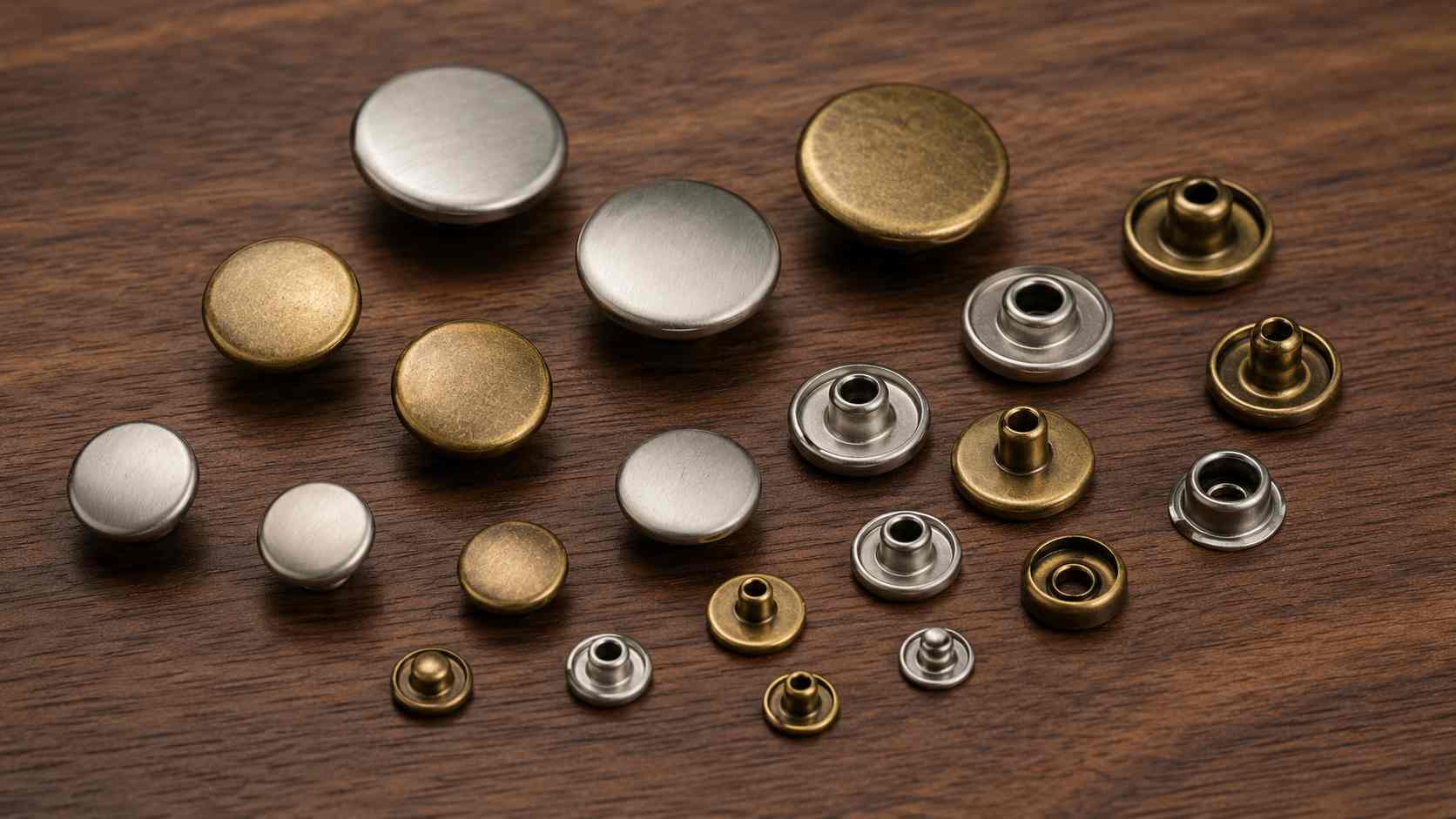
Baocheng (BC New Material) can develop and manufacture customized snap-button products and related precision metal components rather than forcing every project into one nominal catalog geometry. The development process begins with the product’s actual use: target closing and release behavior, substrate construction, package size, finish, cycling expectation, installation equipment and compliance scope.
Customization may include socket or spring structure, stud profile, cap appearance, post or eyelet length, critical dimensional tolerances, material, surface finish, logo details and operating-force targets. Sampling can be performed on the customer’s actual substrate stack so that component dimensions are evaluated after installation, not only as loose metal parts.
This approach addresses common buyer pain points:
- the same part number feels different between lots;
- a snap works on a laboratory swatch but not on the finished multilayer product;
- incoming inspection measures an easy dimension that does not correlate with force;
- a new finish moves the fit outside the original window;
- separately sourced components look compatible but are not dimensionally matched;
- high first-use force causes spring set, substrate damage or user complaints;
- production changes cannot be traced to a cavity, die, finish lot or installation setting.
For a new program, Baocheng can help convert subjective requirements such as “firm but easy to open” into measurable dimensional and force targets, then refine the matched socket–stud system through samples and production-control data.
JSW20 for Magnetic-Sensitive and Corrosive Environments
For projects with needle-detection or other magnetic-sensitivity concerns, Baocheng can supply finished snap products and custom components made from JSW20, its patented proprietary ultra-low magnetic permeability stainless steel. JSW20 is designed to retain extremely low magnetic permeability after forming, addressing a common problem in which conventional material can become more magnetically responsive after stamping and cold working.
JSW20 also offers resistance to chloride-containing corrosive environments. This can help projects that need both reliable detector compatibility and improved corrosion durability, including apparel, bags, protective products and other applications exposed to perspiration, salt or cleaning agents.
The benefit is not simply a material label. Formed geometry, finish, contamination control and the complete detection setup still matter. Baocheng therefore supplies JSW20 as finished hardware or engineered components and can validate it within the dimensional, installation and functional requirements of the customer’s program. Compliance statements such as REACH, RoHS, OEKO-TEX or nickel release should always be tied to the applicable product, finish, test report and project scope.
A Buyer’s Dimensional Approval Checklist
- Identify the exact four-part assembly and revision; do not approve by cap size alone.
- Define the socket feature and stud profile that control engagement.
- State whether limits apply before or after plating and before or after assembly.
- Use datums and axial measurement locations that another laboratory can reproduce.
- Validate the measuring method, fixture force and operator repeatability.
- Calculate loose and tight boundary combinations, then make and test them.
- Measure installed height, alignment and distortion on the actual compressed substrate.
- Correlate dimensions with closing, seating and release force–displacement curves.
- Run cycling or environmental conditioning appropriate to the end use.
- Lock the approved material, finish, tooling and setting conditions through change control.
Conclusion
Snap-button holding behavior is highly sensitive to where and how dimensions are defined. The cap outside diameter identifies appearance; the socket shell defines package space; the retaining opening and stud profile define the active fit; and the post, seating depth and installed height determine whether that fit is reached correctly.
Small changes matter because socket and stud variations combine. A few hundredths of a millimeter on each part can move the complete assembly from the loose boundary to the tight boundary. The solution is not to demand the narrowest tolerance everywhere. It is to identify functionally critical features, measure them with a capable method, allocate tolerances around real process data and verify finished assemblies on the actual substrate.
Baocheng can support this process with custom component geometry, matched tolerances, finish and material options, installed sampling, force testing and JSW20 ultra-low magnetic permeability stainless-steel solutions. The result is a dimensionally traceable snap system designed for stable production—not merely a sample that feels acceptable once.
Focused FAQ
1. Is cap diameter the same as snap size?
Not necessarily. Cap diameter describes the visible face and may identify a catalog family, but it does not define the internal socket opening, stud profile, post length or installed height. Approve the complete component combination.
2. Which dimension has the greatest effect on operating force?
The relationship between the effective socket opening and the active stud profile is usually the first dimensional check. Profile slope, spring structure, finish, alignment and installation also affect the measured result.
3. Can a 0.02 mm change really be noticeable?
Yes, especially when the socket and stud move in opposite directions. A 0.02 mm larger stud combined with a 0.02 mm smaller opening increases diametral interference by 0.04 mm.
4. Why is a caliper reading sometimes misleading?
Calipers measure between two contact points. They can miss lobing, local high spots, profile radii and elastic movement caused by jaw force. Optical, contour or functional-gauge methods may be more appropriate for the critical feature.
5. Should dimensions be specified before or after plating?
The drawing must say which state applies. Because the customer uses finished hardware, final plated dimensions and final functional performance should be included in approval even when in-process dimensions are also controlled.
6. Why can loose components pass but the installed snap fail?
Setting can ovalize the socket, tilt the stud or alter installed height. Post length, die alignment, setting force and substrate compression may move an acceptable loose component outside its functional installed condition.
7. What is a functional gauge?
It is a controlled gauge designed to represent a critical mating condition, such as an opening limit or paired fit. Its geometry, insertion direction and permitted force must be documented and calibrated.
8. Can parts from two suppliers be mixed if the catalog size matches?
Not safely without validation. Trade size and appearance do not guarantee the same active profiles, spring opening, seating depth or tolerances. Test the exact mixed combination at its dimensional boundaries.
9. Is a golden sample enough for quality approval?
No. It is useful as a comparison aid but can wear and cannot define production limits. Pair it with drawings, calibrated inspection, force criteria, substrate details and change control.
10. Which ASTM methods are relevant to snap performance?
ASTM D4846 addresses force to disengage snap fasteners in specified pull directions. ASTM D7142 addresses the holding strength of the prong-ring attachment to the socket or stud. They evaluate different failure modes.
11. Can Baocheng customize the fit instead of only changing the finish?
Yes. Custom development can cover socket or spring structure, stud profile, cap and post dimensions, tolerance allocation, material, finish, logo, operating-force targets and testing on the intended substrate.
12. When should JSW20 be considered?
Consider JSW20 when a project needs extremely low magnetic permeability after forming, such as needle-detection-sensitive applications, and when chloride-corrosion resistance is also valuable. Final suitability should be verified in the customer’s complete detection and use conditions.
#SnapButtonDimensions, #SnapButtonHoldingForce, #SocketDiameter, #StudProfile, #DimensionalTolerances, #SnapButtonInspection, #ForceDisplacement, #CustomSnapButtons, #JSW20, #BCNewMaterial