






Engineering a Snap Button System: Balancing Size, Holding Force, Substrate Strength and Service Life
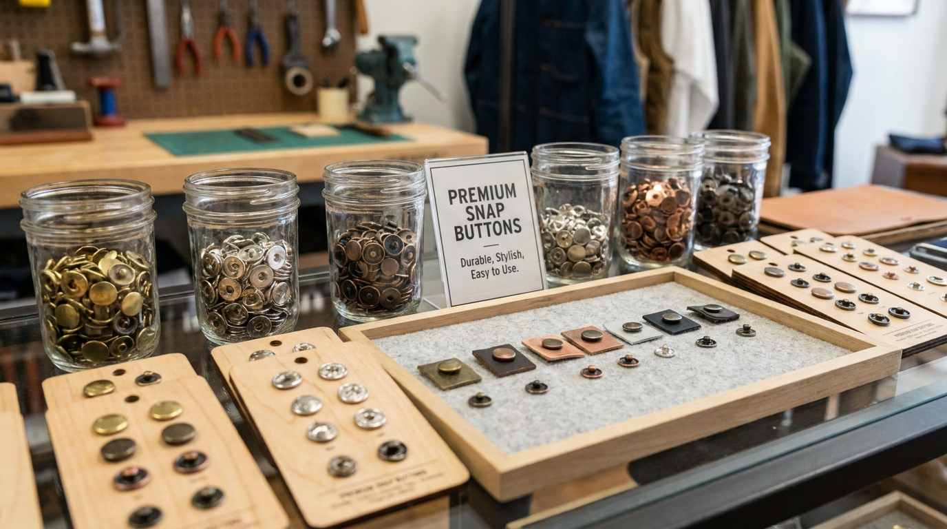
A snap button is often purchased as a small piece of hardware, but it performs as a system. The cap, socket, stud and post or prong must work together. That hardware must then be installed into a fabric, leather, coated textile or multilayer construction without weakening it. Finally, the complete assembly must remain easy enough to operate and secure enough to survive real service.
This creates an engineering balance. Increasing engagement can reduce accidental opening, yet excessive force can strain the substrate or make the product unpleasant to use. A larger cap can spread load over a wider area, yet the active socket and stud geometry—not the visible cap alone—controls engagement. A longer post can accommodate a thicker stack, yet too much unused length can distort the installed assembly. A corrosion-resistant material can protect the hardware, yet service life still depends on finish, setting, contamination and the strength of the surrounding product.
The right goal is therefore not the “strongest” snap. It is a matched snap system whose size, operating force, attachment, environment and service life fit the application. This guide explains how buyers, distributors and product teams can make those tradeoffs in practical language, without relying on complex formulas.
The Short Answer: Engineer the Load Path from the User’s Fingers to the Substrate
Every opening or closing action travels through a chain. The user pushes or pulls the cap. The cap transfers load through the post or prong to the socket or stud. The active pair engages or releases. The installed hardware then transfers the remaining load into the surrounding substrate and reinforcement.
If any link is poorly matched, changing another link may only move the failure. A tighter socket may stop unintended opening but cause the fabric to stretch. A stronger reinforcement may prevent pull-through but expose an overlong post that bends the shell. A thicker finish may improve environmental protection but alter the active fit. System engineering means checking the whole load path rather than optimizing one number in isolation.
| System element | Main engineering question | Typical consequence when mismatched |
|---|---|---|
| Cap and visible profile | Does it fit the product visually and spread user load appropriately? | Local pressure, poor appearance, insufficient finger access or interference with nearby seams |
| Socket and stud | Do the active profiles create the intended closing and release window? | Loose engagement, excessive force, partial seating or rapid wear |
| Post or prong | Does its usable length match the compressed stack and setting method? | Pull-through, bent post, tilted stud, distorted socket or surface marking |
| Substrate and reinforcement | Can the product accept and distribute the installed load? | Tearing, hole growth, coating separation, knit distortion or delamination |
| Setting process | Can the selected dies repeatedly form the attachment without damaging active geometry? | Lot-to-lot force shifts, loose attachment, cosmetic dents or cracked components |
| Service environment | Will use, washing, moisture, salt, dirt and abrasion change the system? | Force drift, corrosion, finish loss, staining, jamming or premature release |
1. Start with the Service Profile, Not the Catalog Size
Before selecting hardware, describe how the product will be used. A snap on a fashion jacket may be operated frequently but carry a modest load. A workwear pocket may be pulled at an angle while the wearer moves. A leather bag may have a thick stack and a relatively rigid reinforcement. A coated cover may see tension, moisture and grit. A washable patient gown may prioritize comfortable operation and repeated care.
The service profile should answer:
- who operates the snap and how much hand force is reasonable;
- how often it is opened and closed during the expected product life;
- whether loading is straight, sideways, peeling, vibrating or mixed;
- whether accidental opening is inconvenient, costly or safety-relevant;
- which substrate constructions and thickness ranges will be used;
- whether the product is washed, dried, cleaned, exposed to perspiration, salt, dust or chemicals;
- what appearance change, force change or attachment damage is unacceptable.
This prevents a common mistake: selecting a snap because it worked on a previous product with a similar appearance. If the load direction, substrate or care cycle changes, the same hardware may behave very differently.
2. Define the Complete Four-Part Combination
The phrase snap button cap socket stud post describes the common four-part architecture, but it should not be treated as four independent catalog items. The cap and socket form one installed side; the stud and post form the other. Their dimensions, material, finish and setting behavior must be approved as a matched combination.
A visible cap diameter cannot identify the internal working geometry. Two snaps can look the same from the outside while using different socket depths, spring structures, stud profiles or post systems. Even components sold under a similar line or trade size may not be interchangeable across product families.
Control the combination with component numbers, revision, material and finish. Distributors should keep matching sets under linked stock codes and prevent loose components from being mixed during repacking. For custom projects, define which component changes are allowed without reapproval. A cap logo change may have little effect on engagement, while a socket spring, stud profile, plating system or post length change can alter the system substantially.
3. Size Has Three Different Meanings
“Snap size” may refer to the visible cap, the active socket and stud family, or the attachment length. These meanings should be separated in drawings and purchase records.
Visible size
The cap diameter and shape affect appearance, finger contact, load distribution and available space. A larger visible surface may spread user load, but it does not automatically increase release force or attachment strength.
Active engagement size
The internal socket and stud geometry controls how the pair enters, seats, retains and releases. This includes active diameters, profile shape, height, spring position and available movement. Small changes can produce a meaningful difference in hand feel even when the cap size is unchanged.
Attachment size
Post or prong length must suit the compressed substrate. Diameter, formed head, flange area and local reinforcement also affect how load reaches the material.
When deciding how to measure press stud size, record these three groups separately. Measure the finished components, because plating or coating can change active dimensions. Then measure the installed sample, because setting can tilt the stud, compress the stack or distort the socket.
Practical rule: do not approve “15 mm” by itself. Approve the visible diameter, matching component family, attachment option and installed construction.
4. Match Post Length to the Substrate Window
A snap button post length chart is a useful starting reference, but the final choice must be confirmed on the real compressed stack. A nominal fabric thickness does not show how the material behaves under the setting dies. Foam, knit, leather, coatings, seam allowances and reinforcement layers compress differently.
Too little usable post length can produce a weak formed attachment or incomplete locking with the mating part. Too much length can buckle, fold unevenly, tilt the active component or force the shell out of shape. Both conditions may pass a quick visual inspection while creating inconsistent force or reduced attachment life.
Build a substrate window rather than approving only one sample:
- identify the thinnest expected production stack;
- identify the normal stack and its construction;
- identify the thickest stack, including seams and reinforcement;
- set samples using production-intent dies and equipment;
- inspect formed attachment, alignment and surrounding material;
- test operation and attachment at all three conditions;
- assign a different post or prong option if one length cannot cover the full range safely.
For a product with multiple materials, it is usually clearer to create approved substrate groups than to force one hardware setup across every construction.
5. Treat Holding Force as a Usable Window
Holding performance includes the ability to stay closed during use, but the user experiences both closing and release. A secure snap that cannot be comfortably operated is not a balanced design. Likewise, a snap that closes easily but opens under ordinary movement does not meet the service requirement.
Questions such as why snap buttons are hard to open often point to a system mismatch rather than a single defective part. Possible causes include an overly aggressive engagement profile, finish buildup, socket distortion during setting, stud tilt, contamination, insufficient finger access or a load direction that peels the snap instead of opening it as intended.
Set a lower and upper boundary:
- the lower boundary protects against incomplete retention and unintended opening;
- the upper boundary protects usability, seams, substrate and nearby construction;
- the initial window should include normal production variation;
- the final window should still be acceptable after the agreed service sequence;
- the test direction should reproduce how the product is actually opened.
Do not chase a single impressive peak value. Review the distribution across multiple samples and lots. Also observe whether each snap fully seats, whether force feels smooth or abrupt, and whether the substrate deforms during operation.
6. Let Substrate Strength Set the Safe Ceiling
The substrate often sets the maximum practical operating force. A rigid leather panel with reinforcement may tolerate loads that would stretch a lightweight knit or tear a thin coated textile. If opening the snap repeatedly pulls the material farther than the hardware travels, the product is already warning that the balance is wrong.
Substrate strength is not one universal number. The relevant behavior may include resistance to pull-through, tear growth, hole enlargement, delamination, coating separation, yarn distortion and repeated flexing. The installed location matters too. A snap near an edge, seam, pocket corner or cutout sees a different load path from one placed in a wide reinforced panel.
For snap fasteners for coated fabric, verify more than the base textile strength. Check whether piercing damages the coating, whether the setting pressure causes cracking, whether the reinforcement bonds to the coating, and whether repeated flexing begins a local delamination. The correct solution may involve a different post, wider load-spreading geometry, a reinforcement patch, revised hole preparation or a lower operating-force target.
Reinforcement should redirect load, not only add thickness
A reinforcement patch works best when it spreads load into a larger stable area. A small, stiff patch can create a sharp boundary where the outer material begins to tear. A very soft patch may add thickness without improving pull-through resistance. The patch material, shape, edge finish, bonding or stitching method and orientation should be part of the approved construction.
7. Engineer the Setting Process with the Hardware
The setting process creates the final geometry. Loose components can measure correctly and still perform poorly after installation. Misalignment, worn tooling, excessive pressure, insufficient pressure or the wrong anvil can distort the socket, tilt the stud or form the post unevenly.
A matched snap button die set should support the cap and active component without crushing them, guide the upper and lower parts into alignment, and form the attachment consistently across the approved thickness range. A die identified only by nominal cap size may not control all critical contact surfaces.
Record the following with the approved sample:
- upper and lower die identification;
- machine or press type;
- product orientation and support method;
- hole preparation or self-piercing condition;
- setting adjustment or approved operating range;
- installed height, alignment and acceptable appearance;
- inspection frequency and reaction to drift;
- tool maintenance and replacement rules.
When a force complaint appears, compare loose components and installed assemblies. If loose parts perform consistently but installed parts do not, the setting process or substrate interaction deserves priority.
8. Design for Service Life, Not Only Initial Approval
Service life is the period during which the installed snap remains acceptable in operation, attachment and appearance. It is not proven by one successful opening. Repeated engagement changes contact surfaces; substrate holes can grow; finishes can polish or wear; moisture and residues can change friction; and the setting may relax as the material is compressed.
Projects requiring washable metal snap buttons need an agreed care sequence that represents the final product. Record washing conditions, drying method, number of treatments, whether the snap is open or closed, and inspection points. After care, check staining, corrosion, coating damage, deformation, attachment security and operating behavior.
Requests for corrosion resistant snap buttons still require application validation. Material, finish, formed edges, trapped moisture, contact with other metals, chloride exposure and cleaning residues all influence the completed assembly. Corrosion resistance should be evaluated together with appearance and operation, because deposits or surface attack can change friction before a component breaks.
A practical service sequence can include:
- initial installed inspection and operating-force check;
- environmental exposure relevant to the product;
- controlled opening and closing cycles;
- intermediate inspections for force drift and local damage;
- final operation and attachment checks;
- comparison with retained unexposed samples from the same lot.
The order should be fixed. Cycling before washing is not equivalent to cycling after washing, because the substrate, finish and contact condition have changed.
9. Use a Tradeoff Matrix Before Changing the Design
When one requirement is changed, review the likely effect on the rest of the system. The table below is a design discussion tool, not a universal prediction; samples on the real product remain necessary.
| Proposed change | Possible benefit | New risk to check |
|---|---|---|
| Increase active engagement | More resistance to unintended release | Higher opening/closing force, substrate strain, setting sensitivity and faster contact wear |
| Increase cap or flange area | Wider load distribution and stronger visual presence | Interference with seams, greater bending leverage or unacceptable appearance |
| Use a longer post | Accommodation of a thicker material stack | Buckling, tilt, shell distortion and inconsistent formed height on thinner areas |
| Add a stiff reinforcement | Improved resistance to local pull-through | Hard edge, stress concentration, added thickness and different setting requirement |
| Change finish or coating | New color, appearance or environmental protection | Dimensional buildup, changed friction, adhesion risk and different wear behavior |
| Reduce operating force | Easier use and lower substrate loading | Insufficient retention under movement, vibration or peel loading |
| Change substrate construction | Lower cost, weight or improved product comfort | Different compression, tear behavior, coating damage and attachment life |
10. Validate Boundary Combinations, Not Only the Best Sample
A development sample often represents a favorable combination: nominal parts, careful installation and a single material panel. Mass production creates a wider range. To prevent surprises, build boundary samples intentionally.
Useful boundary combinations include:
- the thinnest substrate with the longest approved attachment option;
- the thickest substrate with the shortest approved option;
- samples near the lower and upper operating-force limits;
- all approved finishes that can change dimension or friction;
- parts from different tool cavities or forming stations;
- the weakest permitted reinforcement construction;
- samples after the most demanding agreed service condition.
Boundary validation is not the same as deliberately combining unrealistic defects. The aim is to test permitted production conditions that can actually occur. If an allowed combination fails, either the component window, substrate window, setting window or permitted combination list must be changed.
11. Separate the Three Main Failure Paths
| Failure path | What happens | Where to investigate |
|---|---|---|
| Engagement failure | The socket and stud do not seat, release too easily or require excessive force | Matching family, active profiles, finish, deformation, contamination and service wear |
| Attachment failure | The socket, stud, post or prong separates from the installed side | Post/prong choice, formed attachment, tooling, setting adjustment and alignment |
| Substrate failure | The hardware remains assembled but the surrounding product tears, stretches or delaminates | Material strength, reinforcement, hole preparation, edge distance, load direction and operating-force ceiling |
Preserve the failed product before taking it apart. Record which side failed, the user’s pull direction, surrounding material damage, component identity, setting line and service history. A corrective action aimed at the wrong failure path can make another part of the system worse.
12. Use a Validation Ladder from Parts to Product
System validation is easier to manage when it moves through clear levels:
- Component identity: confirm the complete matching family, dimensions, materials, finishes and revisions.
- Loose-pair function: check basic engagement, seating and release without substrate effects.
- Installed panel: use real substrate groups, reinforcement, dies and production-intent settings.
- Boundary panel: test thickness, force, finish and attachment limits.
- Complete product: include real seams, access, user direction and nearby construction.
- Service sequence: combine environment, repeated operation and final acceptance checks.
- Production confirmation: verify multiple lots, cavities, setting lines and traceability records.
Do not skip directly from a loose hand sample to mass production. Each level reveals a different interaction, and later levels should use the same controlled component and substrate definitions approved earlier.
13. What Buyers Should Expect from a Manufacturing Partner
A capable press stud manufacturer should help translate product use into a controlled component-and-setting system. This includes identifying the matching family, reviewing substrate thickness and reinforcement, recommending attachment options, supplying matching dies, defining samples and maintaining change control.
Buyers and distributors should request:
- complete component identification rather than a cap-only description;
- finished dimensions and approved material/finish combinations;
- recommended dies and installation guidance;
- actual-substrate samples covering the expected range;
- initial and post-service performance data under agreed conditions;
- lot and revision traceability for components and finishes;
- notification before material, tooling, geometry, finish or sub-supplier changes;
- a practical reaction process for engagement, attachment and substrate complaints.
This is especially important for distributors who supply the same snap family to several customer applications. A component combination suitable for one material should not be promoted as universal without application validation.
How Baocheng Engineers Custom Snap Button Systems

Baocheng (BC New Material) supplies finished snap-button products and customized precision components. Customization can include cap size and shape, socket and spring structure, stud engagement profile, post or prong dimensions, material, finish, color, logo, opening and closing behavior, matching dies and installation guidance.
Development can begin with the customer’s actual product, drawings or material stack. Baocheng can prepare samples on intended fabrics, leather, coated textiles or multilayer constructions, then compare normal and boundary conditions. This connects component design with real setting and service behavior instead of approving loose hardware alone.
The service addresses common customer pain points:
- a standard size looks correct but does not suit the compressed stack;
- higher holding force causes the material to stretch or tear;
- an acceptable prototype becomes inconsistent across production lots;
- a finish or logo revision changes fit, friction or setting behavior;
- the hardware survives but the coated or laminated substrate fails;
- distributors need controlled matched sets and private-label presentation;
- a product needs low magnetic response together with corrosion resistance;
- the buyer needs one matched solution covering components, substrate, tooling and service checks.
Baocheng can supply standard or customized finished hardware and engineered components. It does not supply JSW20 raw sheet or coil.
JSW20 for Low-Magnetic and Chloride-Exposed Applications
JSW20 is Baocheng’s patented proprietary ultra-low magnetic permeability stainless steel. It is designed to retain extremely low magnetic permeability after forming, addressing the magnetic response that conventional stainless materials can develop during stamping and cold work. This is valuable for appropriate needle-detection-sensitive and other magnetic-sensitive products.
JSW20 also provides resistance to chloride-containing corrosive environments. The combination supports projects that need low magnetic response together with exposure to perspiration, salt, washing or cleaning. Suitable use still depends on the finished geometry, degree of forming, surface condition, chloride concentration, temperature, contact materials and actual service environment.
Material choice must be integrated into the snap system. JSW20 does not remove the need to validate geometry, setting, operating force, substrate strength and service life. Baocheng supplies JSW20 as finished snap products or customized components. REACH, RoHS, OEKO-TEX, nickel-release and other statements should be tied to the applicable product, finish, report and project scope.
Engineering Decision Checklist
- Describe the user, opening frequency, load direction and consequences of accidental release.
- Identify the complete cap, socket, stud and post/prong combination.
- Separate visible size, active engagement size and attachment length.
- Define minimum, normal and maximum compressed substrate stacks.
- Set usable lower and upper operating-force boundaries.
- Confirm the substrate can tolerate the selected operating-force ceiling.
- Design reinforcement to spread load without creating a hard tear boundary.
- Approve matched tooling, installation settings and maintenance controls.
- Test all approved materials and finishes that can change fit or service behavior.
- Build realistic boundary samples rather than approving one favorable prototype.
- Separate engagement, attachment and substrate failure during analysis.
- Validate the complete product through its intended service sequence.
- Keep components, lots, revisions, finishes and setting lines traceable.
- Require reapproval when a change can affect the system balance.
Conclusion
A snap button system is successful when its parts, substrate, setting process and service environment remain balanced. Size must identify more than the visible cap. Holding force must be secure without exceeding the product’s usable or structural limits. Post or prong selection must match the compressed material. Reinforcement must distribute load. Setting tools must create repeatable final geometry. Service testing must confirm that the system remains acceptable after real use and exposure.
Optimizing one feature in isolation can simply move the failure elsewhere. The better approach is to follow the load path, define practical boundaries, validate realistic combinations and keep the approved system under change control.
Baocheng can support this process with customized snap components, matched tooling, actual-substrate sampling, operating-behavior development, finish and logo options, production controls and JSW20 ultra-low magnetic permeability stainless-steel solutions. The result is not merely a stronger snap, but a system designed for the customer’s product and service conditions.
Focused FAQ
1. Why should a snap button be engineered as a system?
Because engagement, attachment, substrate strength, setting and service exposure interact. Improving one part without checking the others can move the failure to a different location.
2. Does a larger cap create more holding force?
Not automatically. The active socket and stud geometry controls engagement. A larger cap mainly changes appearance, finger contact, available space and load distribution.
3. How should post length be selected?
Select it from the compressed minimum, normal and maximum substrate stacks, then confirm formed attachment, alignment, operation and pull-through resistance with production-intent tooling.
4. Why can a very tight snap damage a product?
High operating force can stretch fabric, enlarge holes, stress seams, delaminate coatings or pull the installed hardware from the substrate during repeated use.
5. Is substrate failure the same as hardware pull-out?
No. Hardware attachment can remain intact while the surrounding fabric, leather, coating or laminate tears or separates. The failed load-path location should be recorded.
6. What does reinforcement need to do?
It should spread load into a wider stable area without creating a hard edge, excessive thickness or another local stress concentration.
7. Why do setting dies affect holding force?
The dies create the final installed geometry. Incorrect support, pressure or alignment can distort the socket, tilt the stud or form the post unevenly.
8. What should service-life validation include?
It should combine relevant environmental exposure, controlled opening and closing, intermediate inspections, final operating behavior, attachment checks and appearance criteria.
9. Why are boundary samples necessary?
They show whether permitted thickness, finish, force and production combinations remain functional, rather than proving only one carefully prepared nominal prototype.
10. Can one snap combination be used on every substrate?
Not safely by assumption. Different substrates compress, tear, flex and delaminate differently. Each approved construction or substrate group needs representative validation.
11. What can Baocheng customize in a snap system?
Baocheng can customize cap, socket, spring, stud, post or prong geometry; material, finish, color and logo; operating behavior; matching dies; and application sampling on the customer’s substrate.
12. Where does JSW20 add value?
JSW20 provides extremely low magnetic permeability after forming together with chloride-corrosion resistance for appropriate needle-detection-sensitive, magnetic-sensitive and corrosive-service projects.
#SnapButtonEngineering, #SnapButtonSystem, #HoldingForce, #SubstrateStrength, #PostLength, #SnapButtonSetting, #ServiceLife, #CustomSnapButtons, #JSW20, #BCNewMaterial